10 Shear Loading in Beams
Chapter 9 showed us how to calculate bending stresses in beams and how to design beams to resist bending stress. Transverse loading applied to beams will also create internal shear loads and therefore shear stresses that must be calculated and accounted for (Figure 10.1).
This chapter first reviews an important geometric property known as the first moment of area and demonstrates how to calculate it for common beam cross-sections in Section 10.1. Section 10.2 discusses transverse shear stresses in beams and how to calculate them. Section 10.3 covers shear flow, which is useful for beams with cross-sections formed by joining two or more parts with fasteners such as nails.
10.1 First Moment of Area
Click to expand
Shear stress in an object depends on the internal shear force and the shape of the cross-section. One important geometric property used in this chapter is the first moment of area. This property was introduced in Section 8.1 and was used when determining the centroid of an area. Recall we used Equation 8.1 to break down simple cross-sections into a number of composite parts. When finding the centroid of these composite areas we modified the equation slightly to
\[ \bar{y}=\frac{\sum y_i A_i}{\sum A_i}=\frac{y_1 A_1+y_2 A_2+\ldots}{A_1+A_2+\ldots} \]
We can rewrite this equation in its integral form.
\[ \bar{y}=\frac{\int y d A}{\int d A} \]
The numerator in this equation is the first moment of area. It will be given the symbol Q.
\[ Q=\int y d A \]
Similarly, for the purposes of this text we can write
\[ \boxed{Q=\sum y_i A_i=y_1 A_1+y_2 A_2+\ldots}\text{ ,} \tag{10.1}\]
Q = First moment of area [m3, in.3]
y = Vertical distance from neutral axis to centroid of area A [m, in.]
A = Area above (or below) point of interest [m2, in.2]
In Section 8.1 we performed this calculation relative to some convenient reference axis to determine the location of the centroid of an area (such as in Example 8.3). Ai represents the area of each composite part, and yi represents the distance from the reference axis to the centroid of each composite part.
The first moment of area can actually be calculated around any axis. The maximum value will always occur at the centroid of the cross-section (i.e., the neutral axis for pure bending), so many problems will involve finding the first moment of area at the neutral axis, but there are also cases where finding the first moment of area around some other axis is required. Note that the axis should be perpendicular to the shear force, so a vertical load requires us to use a horizontal axis.
To calculate the first moment of area around an axis, first draw a line through this axis. We may choose to use either the area above this axis or the area below it, whichever is simpler. The answer will be the same either way. Break down this area into composite parts (if necessary) and apply \(Q=\sum y_i A_i\), where Ai is the area of each composite part and yi is the perpendicular distance between the overall centroid of the cross-section and the centroid of each composite part. Note that to measure this distance we must first find the location of the overall centroid of the cross-section. Figure 10.2 illustrates this process for finding Q at the neutral axis and at another axis for two different cross-sections.
Example 10.1 demonstrates this process to find the first moment of area around the neutral axis of a T cross-section. This example is solved twice, once using the area below the neutral axis and once using the area above.
Example 10.2 uses the same cross-section and demonstrates calculating the first moment of area around a different axis on the cross-section.
Example 10.1
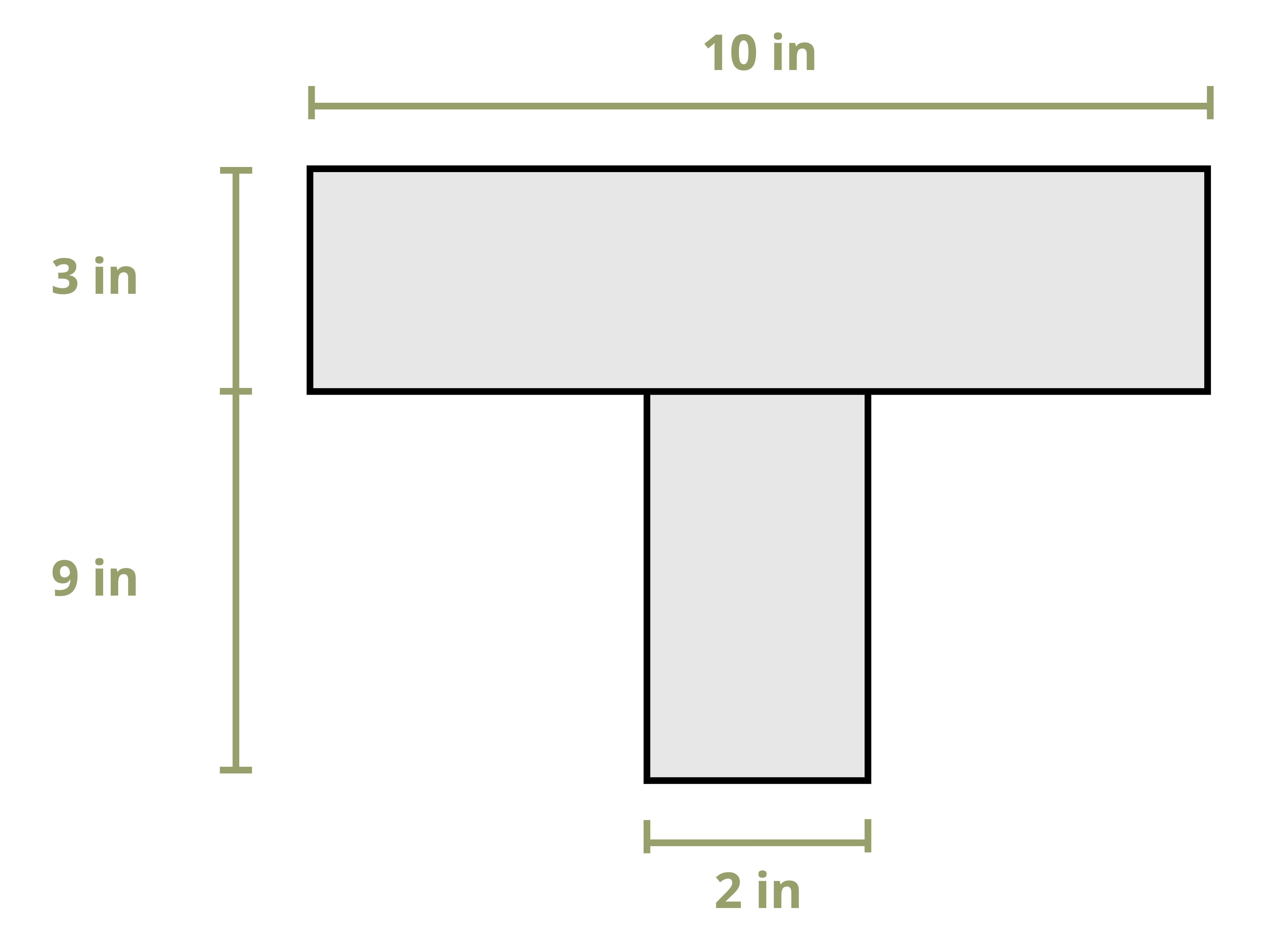
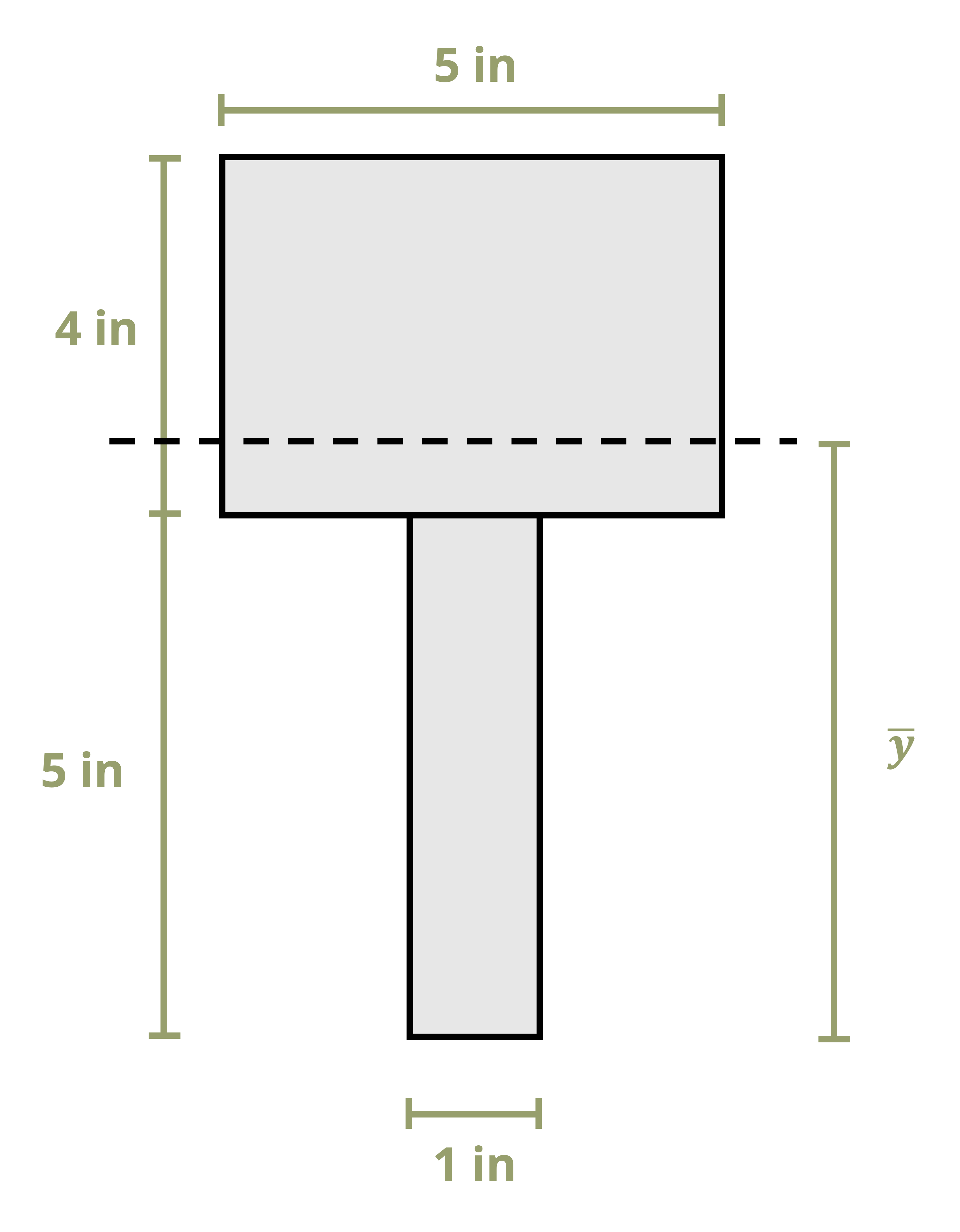
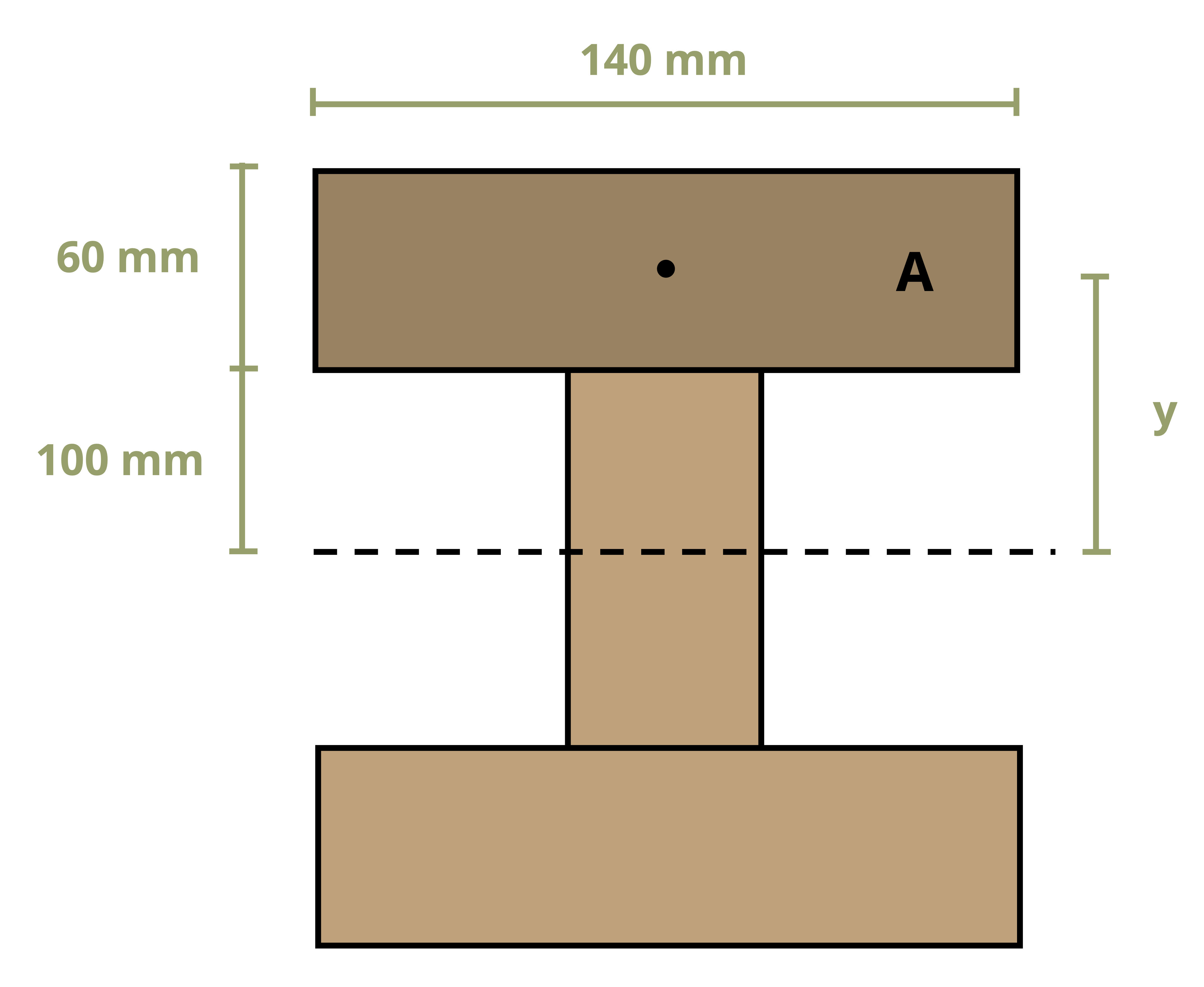
A beam has the T-shaped cross-section shown.
Determine the first moment of area around the neutral axis of the cross-section.
First determine the y coordinate of the centroid of the cross-section. Consider the area as two rectangles and use the method applied in Section 8.1. We will choose a reference point at the bottom of the section to calculate the centroid.
\[ \begin{aligned} & y_1=4.5{~in.},~ A_1=18{~in.}^2 \\ & y_2=10.5{~in.},~ A_2=30{~in.}^2 \\ & \bar{y}=\frac{(4.5{~in.} * 18{~in.}^2)+(10.5{~in.} * 30{~in.}^2)}{18{~in.}^2+30{~in.}^2}\\ & \bar{y}=8.25{~in.}~~\text{from the bottom of the section (our reference point) } \end{aligned} \]
Note that since this section is simple, only two shapes, we need not create a table as we did in Section 8.1. This is a simplified version of the table, but the calculation is exactly the same.
Now draw a horizontal line through the point of interest. In this case the point of interest is the neutral axis. Use either the area above this line or the area below this line to determine the first moment of area around the neutral axis. We’ll solve it both ways to demonstrate that we obtain the same answer either way.
Area below the neutral axis:
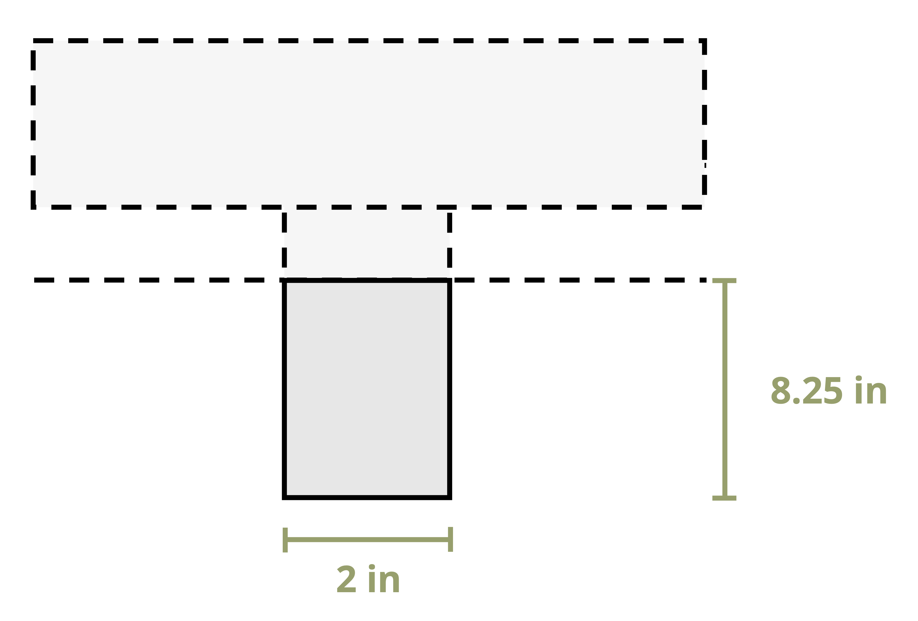
This area is a simple rectangle. Recall that Q = yA, where A is the area of the rectangle and y is the vertical distance between the neutral axis and the centroid of the rectangle.
\[ \begin{aligned} & y=\frac{8.25{~in.}}{2}=4.125{~in.} \\ & A=8.25{~in.} * 2{~in.}=16.5{~in} ^2 \\ & Q=y A=4.125{~in.} * 16.5{~in.}^2=68.1{~in.}^3 \end{aligned} \]
Area above the neutral axis:
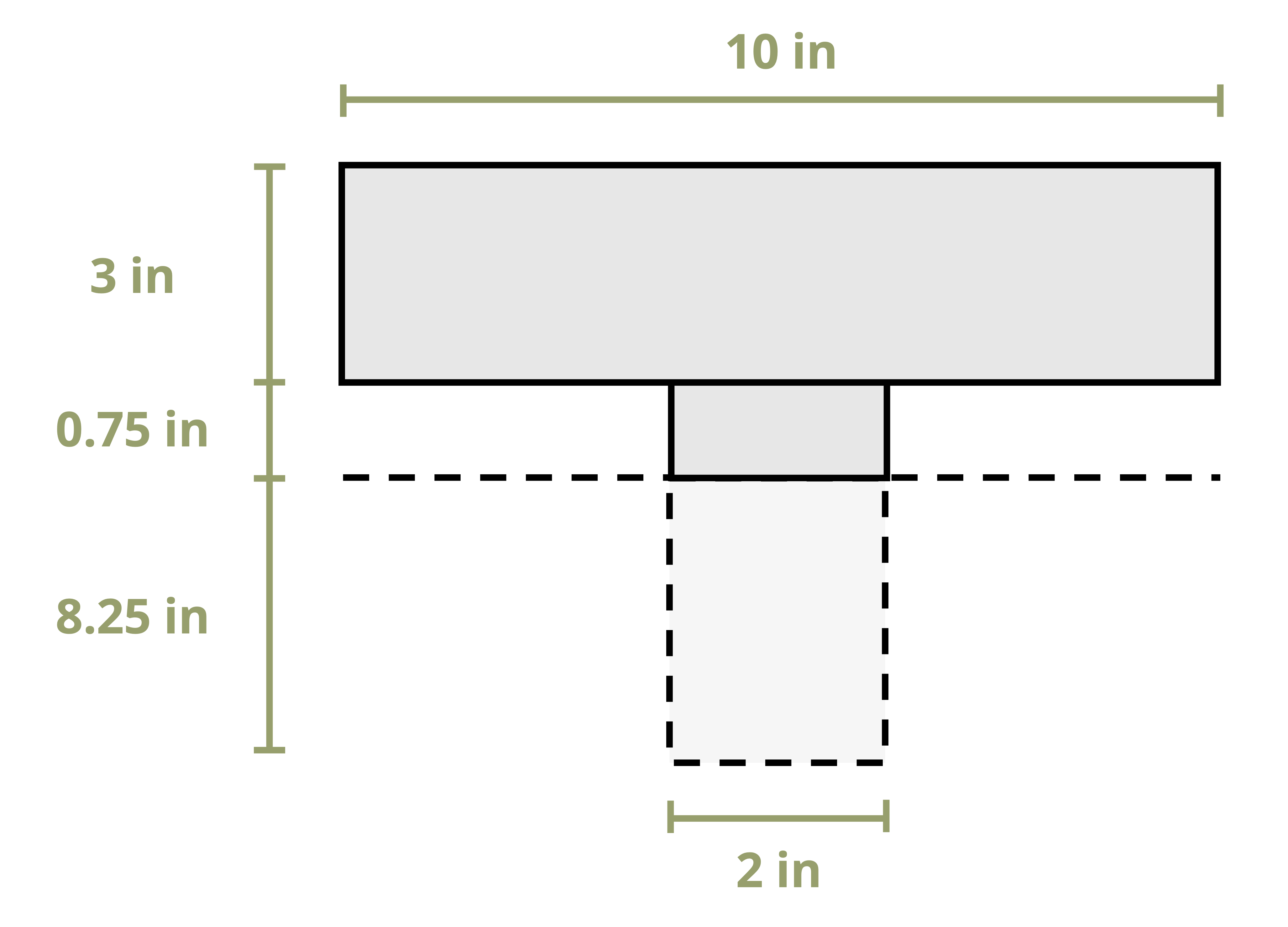
This area can be split into two rectangles. Here we’ll use \(Q=\sum y_i A_i=y_1 A_1+y_2 A_2\).
\[ \begin{aligned} & y_1=\frac{0.75{~in.}}{2}=0.375{~in.} \\ & A_1=0.75{~in.} * 2{~in.}=1.5{~in.}^2 \\ & y_2=0.75{~in.}+1.5{~in.}=2.25{~in.} \\ & A_2=10{~in.} * 3{~in.}=30{~in.}^2 \\ & Q=(0.375{~in.} * 1.5{~in.}^2)+(2.25{~in.} * 30{~in.}^2)=68.1{~in}^3 \end{aligned} \]
Whether we use the area above the neutral axis or the area below the neutral axis, the answer Q = 68.1 in.3 is the same. We may choose to use whichever area seems simpler to work with.
Example 10.2
The T-shaped cross-section from Example 10.1 is repeated here.
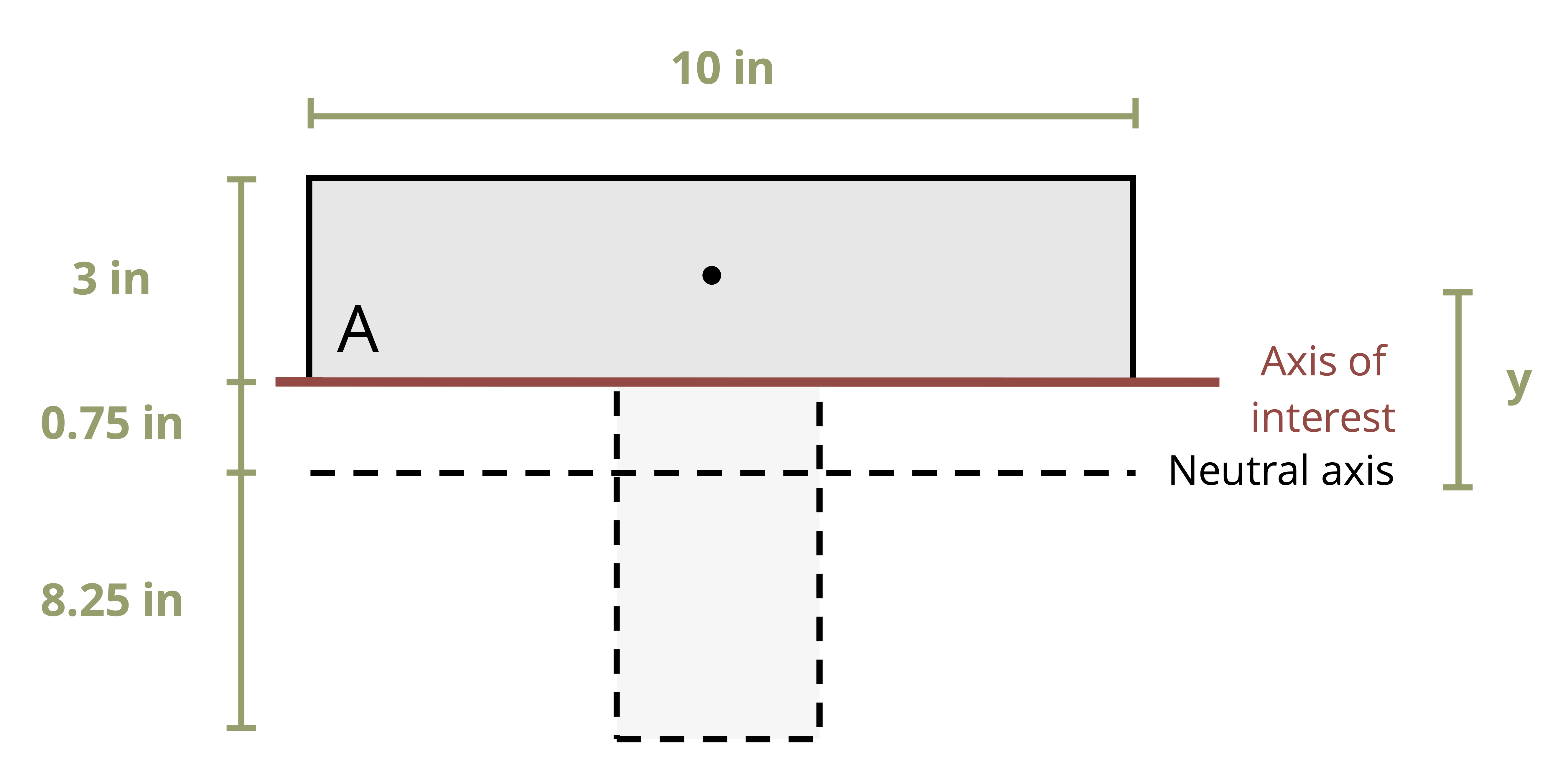
Determine the first moment of area around an axis passing through the interface between the flange and the web.
We need to first determine the y coordinate of the centroid of the cross section, which we did in Example 10.1. The results are shown below.
\(\bar{y}=8.25{~in.}\) from the bottom of the cross-section.
Now draw a horizontal line through the point of interest. In this case the point of interest is the seam between the two boards. As demonstrated in Example 10.1, we may use either the area below this line or the area above this line to determine the first moment of area.
Area above the line:
This area is a simple rectangle. Recall that Q = yA, where A is the area of the rectangle and y is the vertical distance between the neutral axis and the centroid of the rectangle.
Note that the perpendicular distance is always measured to the neutral axis, not to the seam between the two boards.
\[ \begin{aligned} & y=0.75{~in.}+1.5{~in.}=2.25{~in.} \\ & A=10{~in.} * 3{~in.}=30{~in.}^2 \\ & Q=y A=2.25{~in.} * 30{~in.}^2=67.5{~in.}^3 \end{aligned} \]
As an additional exercise, try using the area below the seam between the two boards to calculate Q = 67.5 in.3.
Simple cross-sections such as rectangles and circles are commonly used for beams. For these simple cross-sections we can derive standard solutions for the maximum first moment of area (Qmax). Recall that this always occurs at the neutral axis of the cross-section.
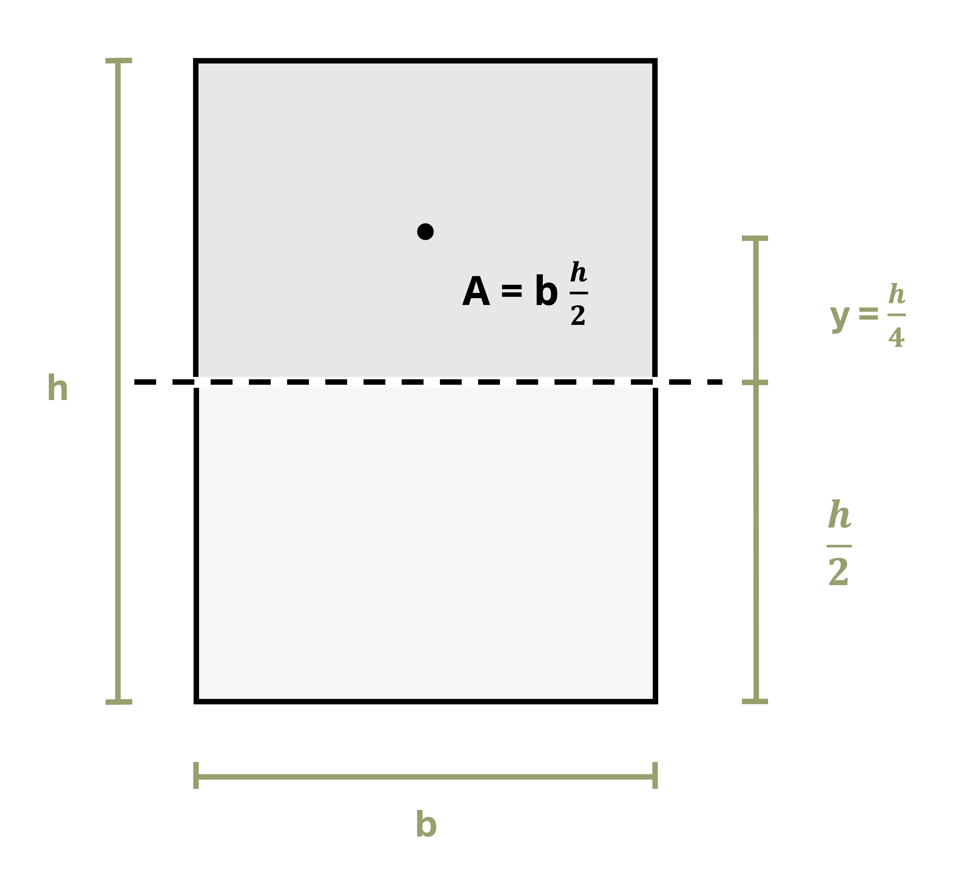
For a rectangle of base b and height h (Figure 10.3), the neutral axis will be at \(y=\frac{h}{2}\). Drawing a line along the neutral axis and taking the area above this line results in \(A=b \frac{h}{2}\). The distance between the centroid of this area and the neutral axis of the cross-section will be \(y=\frac{h}{4}\). Thus for a rectangular cross-section the equation is
\[ Q_{\max }=\frac{h}{4} \frac{b h}{2}=\frac{b h^2}{8}\text{ .} \]
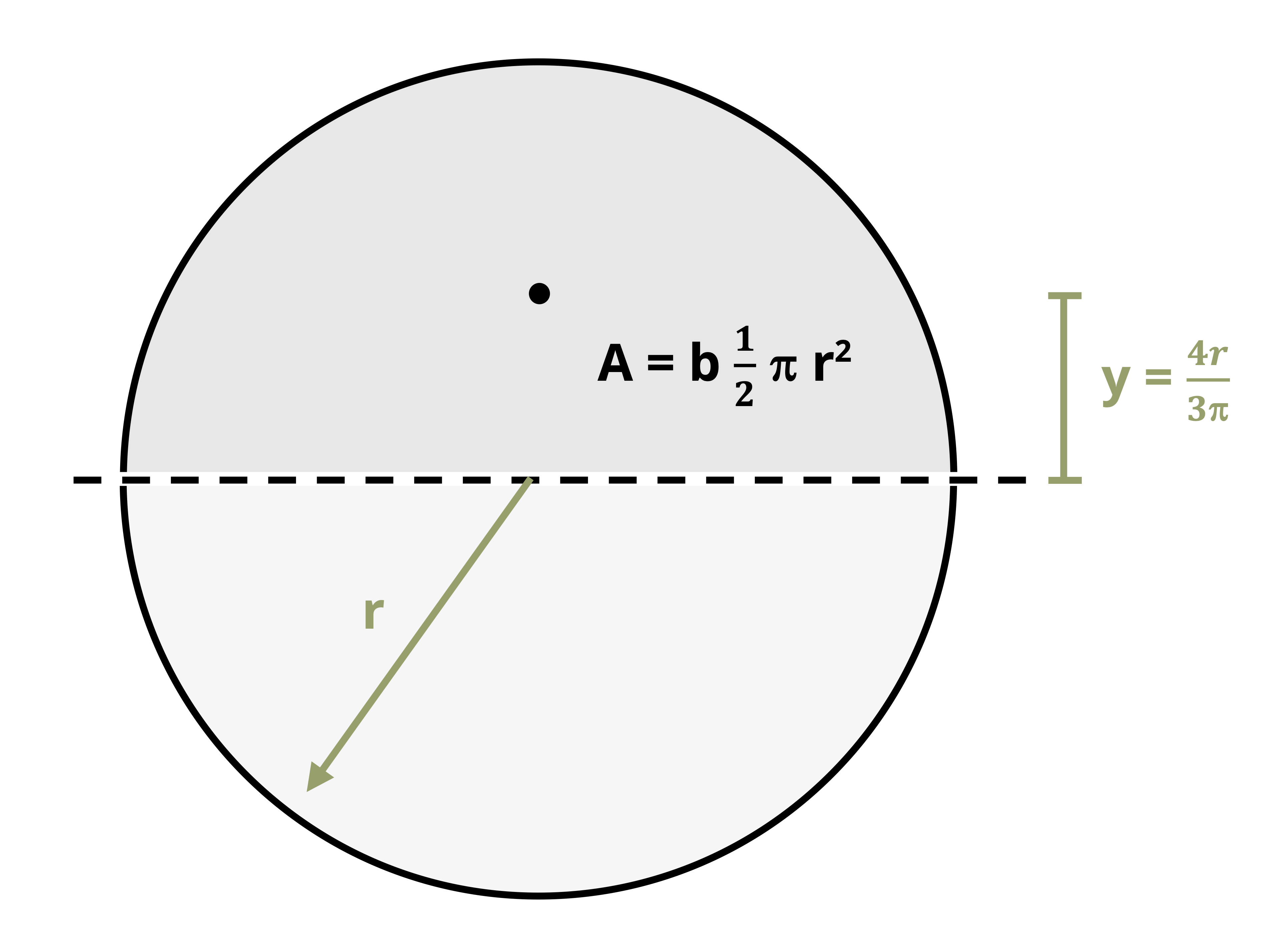
For a circular cross-section of radius r (Figure 10.4), the area above the neutral axis is semicircle, so \(A=\frac{1}{2} \pi r^2\). The distance from the centroid of the semicircle to the neutral axis is \(y=\frac{4 r}{3 \pi}\). Thus for a circular cross-section the equation is
\[ Q_{\max }=\frac{4 r}{3 \pi} \frac{1}{2} \pi r^2=\frac{2}{3} r^3 \]
Note that both of these approaches are used only for finding the first moment of area at the neutral axis (Qmax). If the first moment of area around any other axis is required, these shortcuts will not work and the general process will need to be used.
10.2 Shear Stress
Click to expand
Section 2.2 taught us about average shear stress.
\[ \tau_{avg}=\frac{V}{A} \]
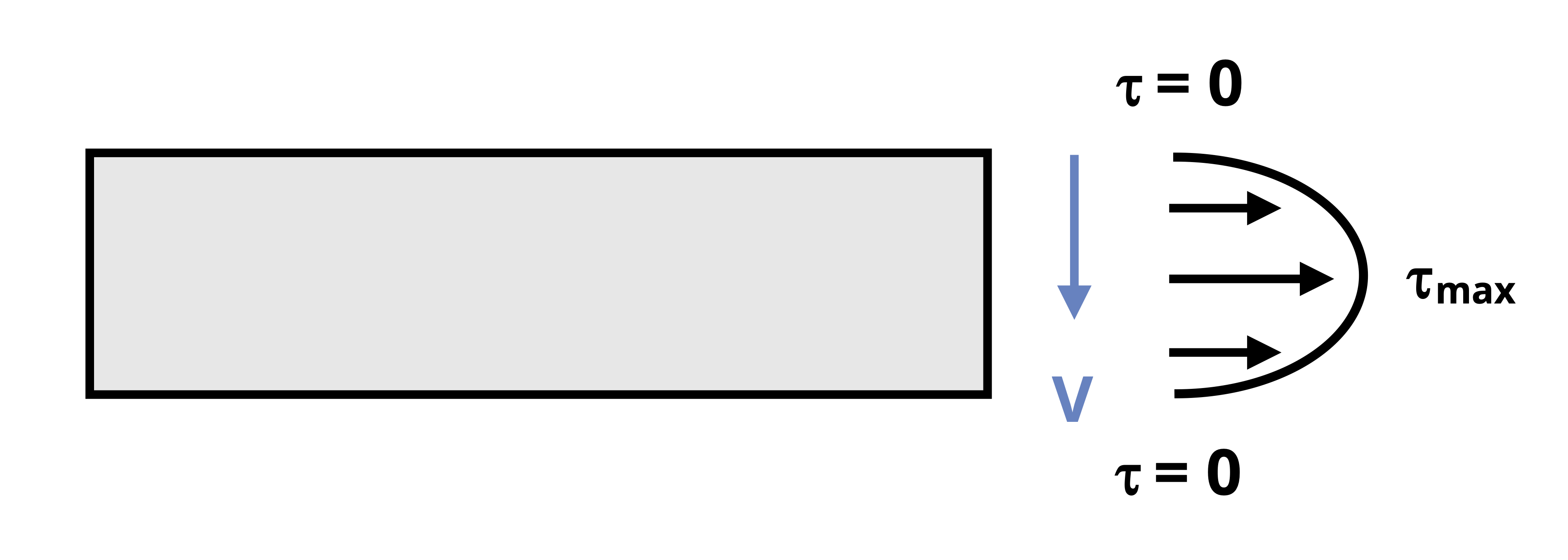
This is the average shear stress on a cross-section, but shear stress actually varies through the height of the section (Figure 10.5). For a vertical internal shear force, the shear stress is zero at the top and bottom of a cross-section and maximum at the neutral axis. Shear stress varies in a parabolic fashion. Because average shear stress does not provide a full picture, it is often necessary to calculate the shear stress at a specific point on the cross-section instead.
To derive the shear stress formula begin by examining a small 2D element on a body subjected to an internal shear force (Figure 10.6). If this element is in equilibrium, a shear force applied to one face of this element must also produce shear forces (and therefore shear stresses) on the other faces of the element.
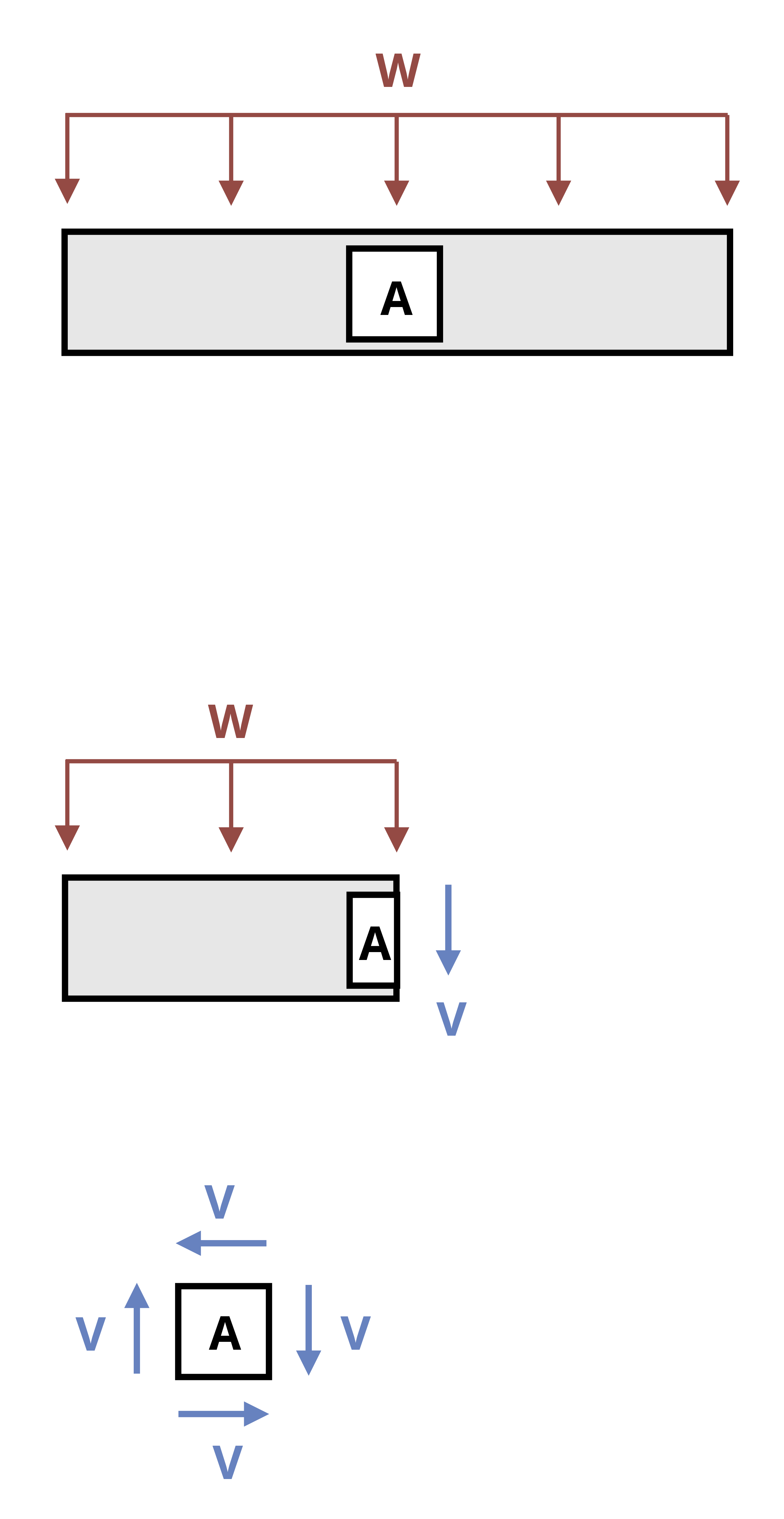
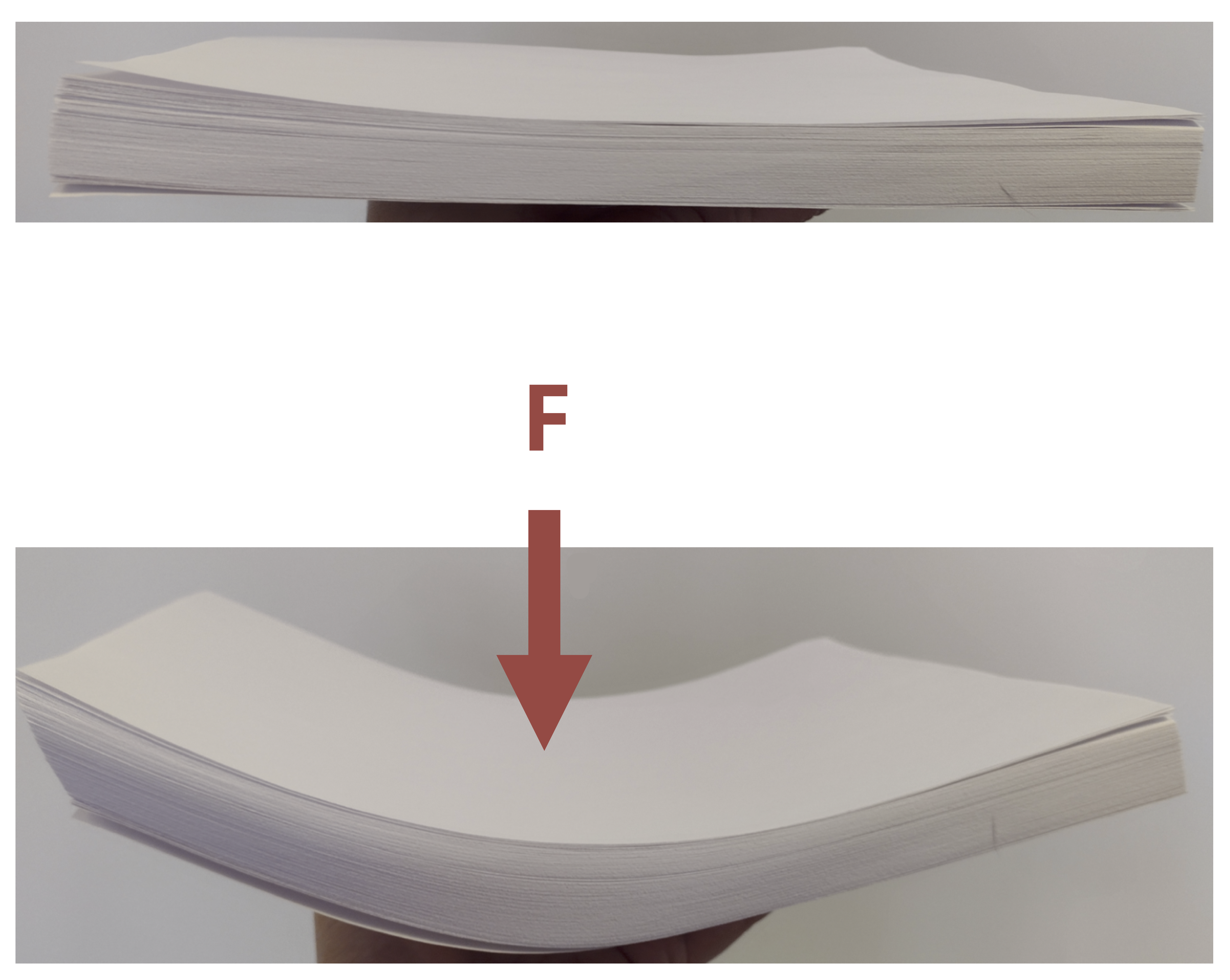
Thus an element experiencing a vertical shear stress also experiences a horizontal shear stress. This is known as the complementary property of shear. This effect can be seen by forming a “beam” out of a stack of paper and applying a vertical force. The pieces of paper slide horizontally relative to each other (Figure 10.7).
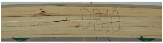
Another example is a wooden beam that fails due to transverse shear. In such beams cracks tend to appear horizontally even though the applied load is vertical. This is due to horizontal shear stress between the layers of the wood (Figure 10.8).
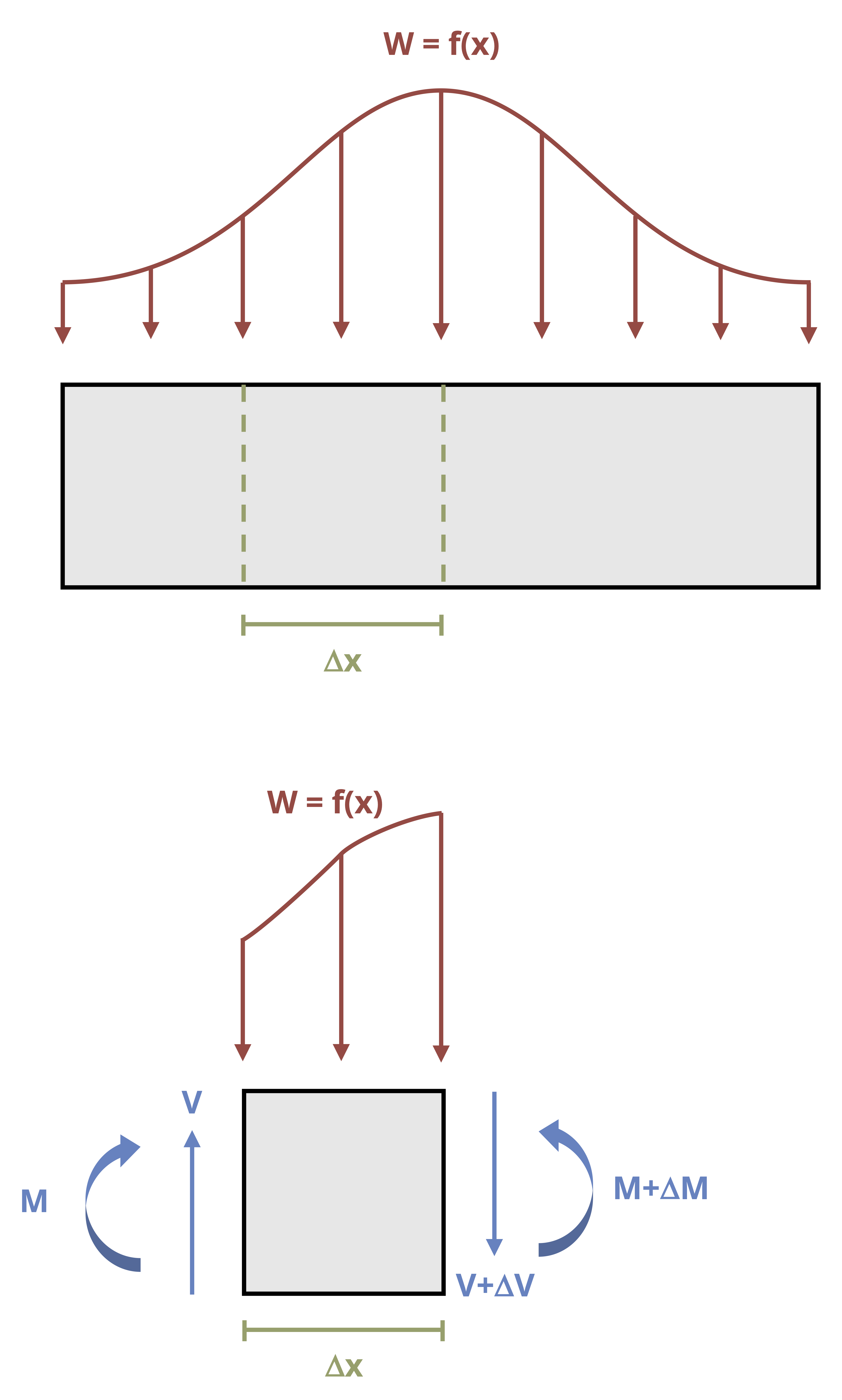
Imagine a beam subjected to an arbitrary vertical load. Consider a small cross-section of width Δx (Figure 10.9). This cross-section is subjected to an external load, an internal shear force on each side of the cross-section, and an internal bending moment on each side of the cross-section. The two shear forces and two bending moments are not necessarily equal.
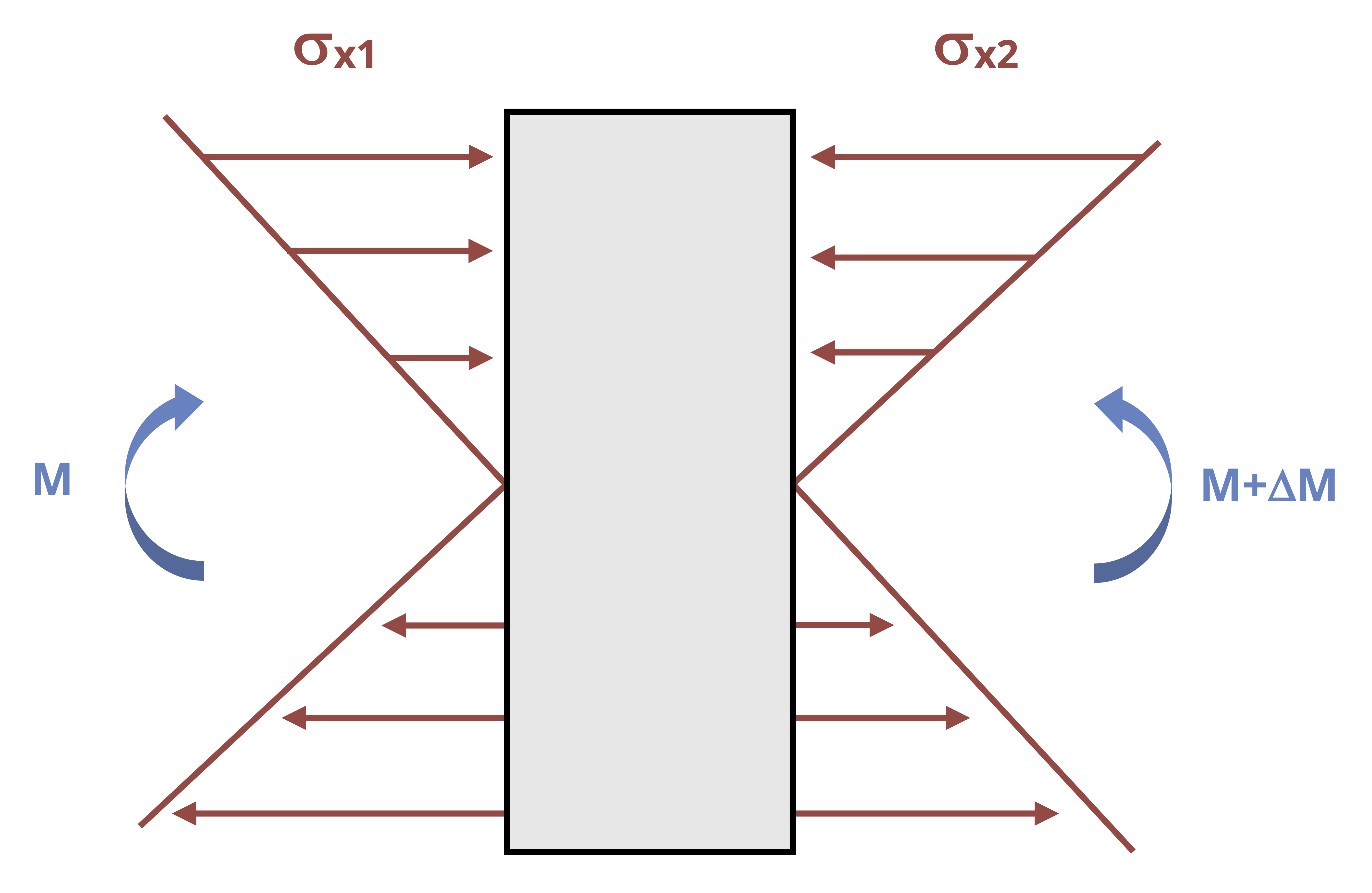
By considering horizontal equilibrium, we do not need to account for the vertical loads (V, V + ΔV, and w). From the flexure formula (Equation 9.2) the bending moments (M and M + ΔM) will create horizontal stresses (Figure 10.10) equal to
\[ \sigma_{x 1}=\frac{M y}{I} \]
and
\[ \sigma_{x 2}=\frac{(M+\Delta M) y}{I} \]
Since \(F=\sigma A\), we can determine the total force applied by each bending moment.
\[ F_1=\int \frac{M y}{I} d A \]
and
\[ F_2=\int \frac{(M+\Delta M) y}{I} d A \]
Each force is tensile in part of the beam and compressive in part of the beam. When calculated across the entire cross-section, these forces will sum to zero. However, if we consider only part of the cross-section, the forces do not sum to zero (Figure 10.11). For the beam to be in equilibrium, there must be a horizontal shear force. For now, we’ll call this force F’ and derive an equation for the shear stress it creates.
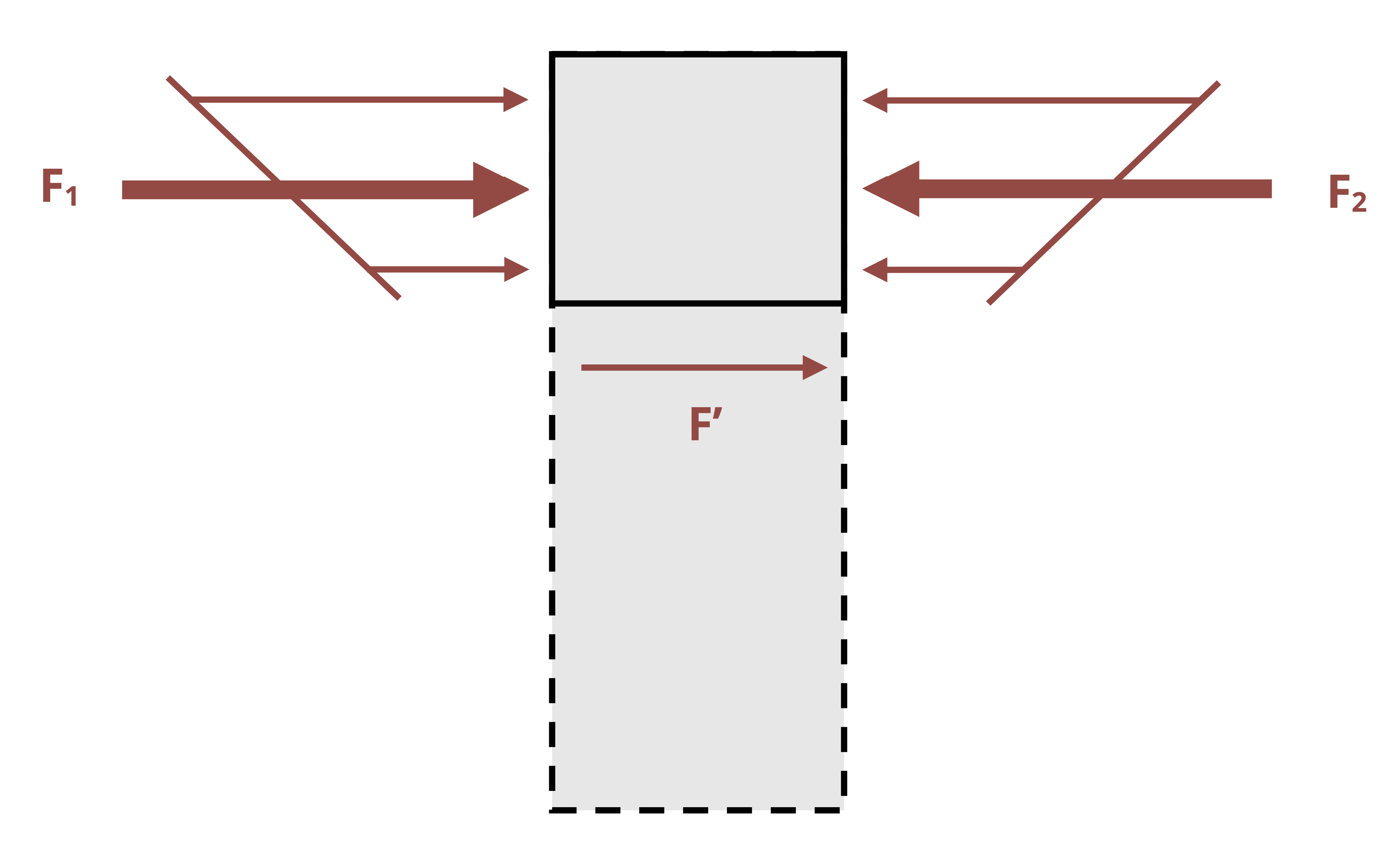
By equilibrium obtain
\[ \begin{aligned} & \sum F_x=F^{\prime}+\int \frac{M y}{I} d A-\int \frac{(M+\Delta M) y}{I} d A=0 \\ & F^{\prime}=-\int \frac{M y}{I} d A+\int \frac{M y}{I} d A+\int \frac{\Delta M y}{I} d A \\ & F^{\prime}=\int \frac{\Delta M y}{I} d A=\frac{\Delta M}{I} \int y d A \end{aligned} \]
Once the constants are taken out of the integral, the remaining integral is just the first moment of area, Q.
\[ F^{\prime}=\frac{\Delta M}{I} Q \]
We can calculate the transverse shear stress from \(\tau=\frac{V}{A}\), where V = F’ and A is the area of the cross-section that force F’ acts on. This area will be the width, Δx, multiplied by the thickness of the beam, t.
\[ \tau=\frac{V}{A}=\frac{F^{\prime}}{\Delta x t}=\frac{\Delta M Q}{\Delta x I t} \]
From Section 7.2 we know that the change in moment with respect to x is equal to the shear force, V.
\[ \frac{\Delta M}{\Delta x}=V \\ \]
\[ \boxed{\tau=\frac{VQ}{It}}\text{ ,} \tag{10.2}\]
τ = Transverse shear stress at a point on the cross-section [Pa, psi]
V = Internal shear force at the cross-section [N, lb]
Q = First moment of area at the point of interest on the cross-section [m3, in.3]
I = Second moment of area of the cross-section [m4, in.4]
t = Thickness of the cross-section [m, in.]
This is the transverse shear stress equation, allowing us to calculate the transverse shear stress at any point on a cross-section. This is often more useful than simply calculating the average shear stress across the entire cross-section.
Example 10.3 demonstrates calculation of the maximum transverse shear stress in a simply supported beam with a circular cross-section.
Example 10.3
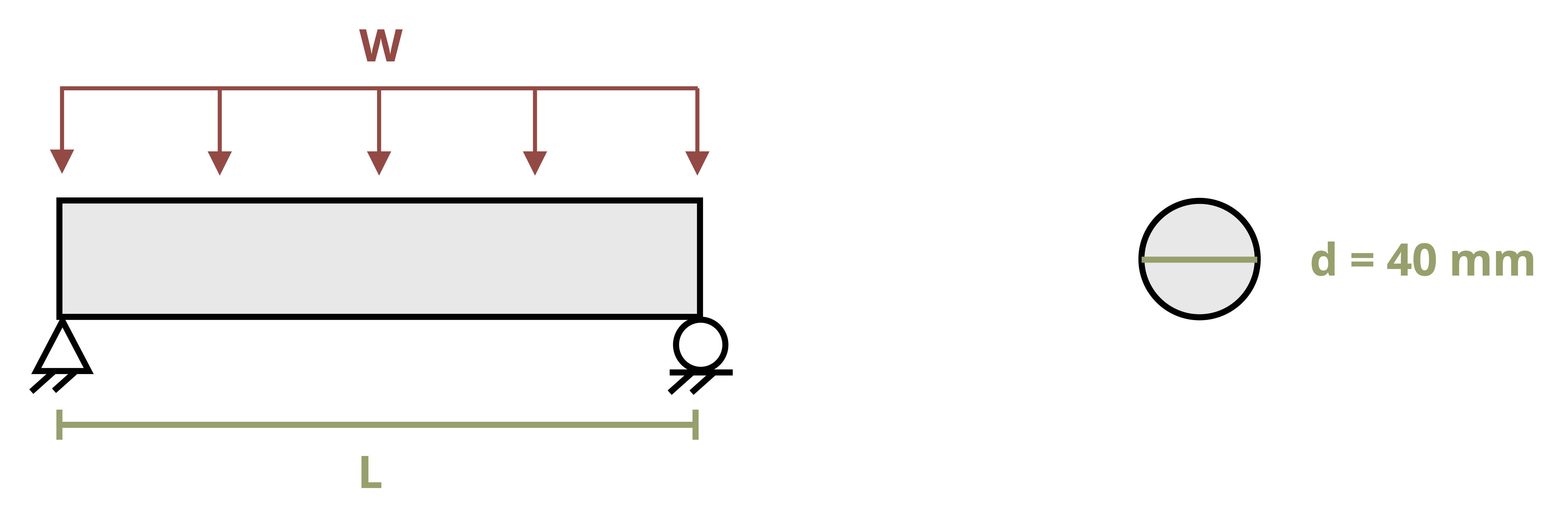
A simply supported beam with the circular cross-section shown is subjected to a uniformly distributed load w = 30 kN/m across its entire length L = 8 m.
Determine the maximum shear stress that occurs in the beam.
The shear stress can be calculated from \(\tau=\frac{V Q}{I t}\). The maximum shear stress will occur when V and Q are at their maximum values.
The maximum shear force, Vmax, can be found by drawing a shear force diagram. Start with a free body diagram (FBD) of the beam and use this to sketch the shear force diagram, employing the graphical method of Section 7.4. The loading and supports are symmetric, so each support will resist half the applied load.
\[ A=B=\frac{w L}{2}=\frac{30\frac{kN}{m} * 8{~m}}{2}=120{~kN} \]
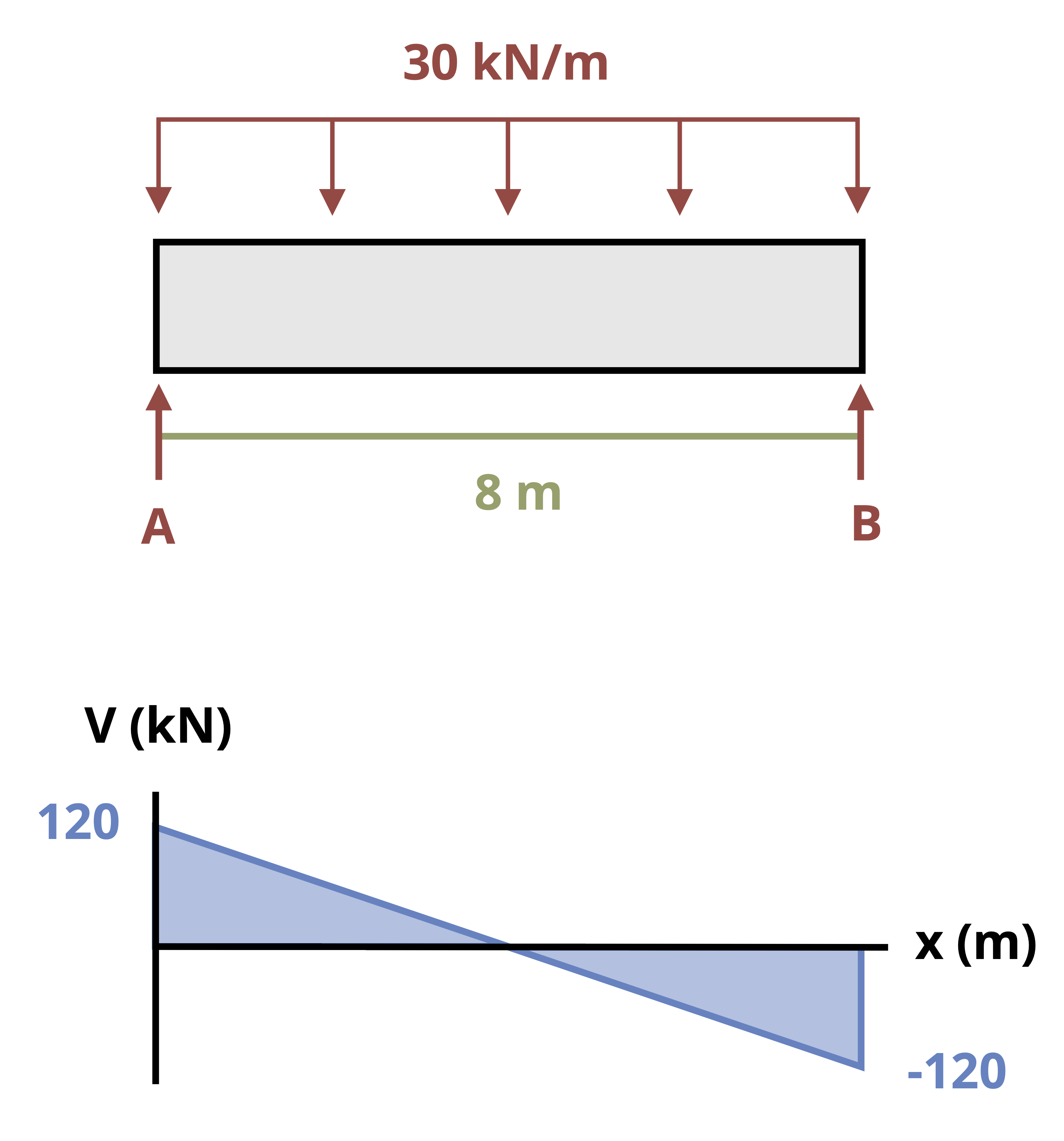
It is apparent that the maximum shear force in the beam is Vmax = 120 kN. This occurs at the supports.
The second moment of area for the circular cross-section is given by
\[ I=\frac{\pi}{4} r^4=\frac{\pi}{4}(0.02{~m})^4=1.257 \times 10^{-7}{~m}^4 \]
The maximum first moment of area, Qmax, occurs at the neutral axis of the cross-section. For a circular cross-section, as demonstrated in the text, that is
\[ Q_{max}=\frac{2}{3}r^3=\frac{2}{3}(0.02{~m})^3=5.33\times10^{-6}{~m}^3 \]
The thickness of the cross-section at the neutral axis equals the diameter, t = 0.04 m.
With all the terms known, we can now calculate the maximum shear stress in the beam.
\[ \tau=\frac{V Q}{I t}=\frac{120,000{~N} * 5.33 \times 10^{-6}{~m}^3}{1.257 \times 10^{-7}{~m}^4 * 0.04{~m}}=127\times10^6\frac{N}{m^2}=127{~MPa} \]
Note that the first moment of area will always be at its maximum value at the cross-section’s neutral axis. Since shear stress \(\tau=\frac{VQ}{It}\), the maximum shear stress often occurs at the neutral axis too. This will be true if the thickness, t, of the cross-section is uniform (e.g., a rectangular cross-section) or at its thinnest at the neutral axis (e.g., a wide-flange beam).
However, if thickness t is larger at the neutral axis than at another point in the beam, the maximum shear stress will possibly occur at the point where the thickness decreases even though Q will be smaller at this location than at the neutral axis. In these cases it’s best to calculate the shear stress at both the neutral axis and the location where the thickness decreases.
Example 10.4 demonstrates how to calculate the maximum transverse stress at a cross-section of varying thickness.
Example 10.4
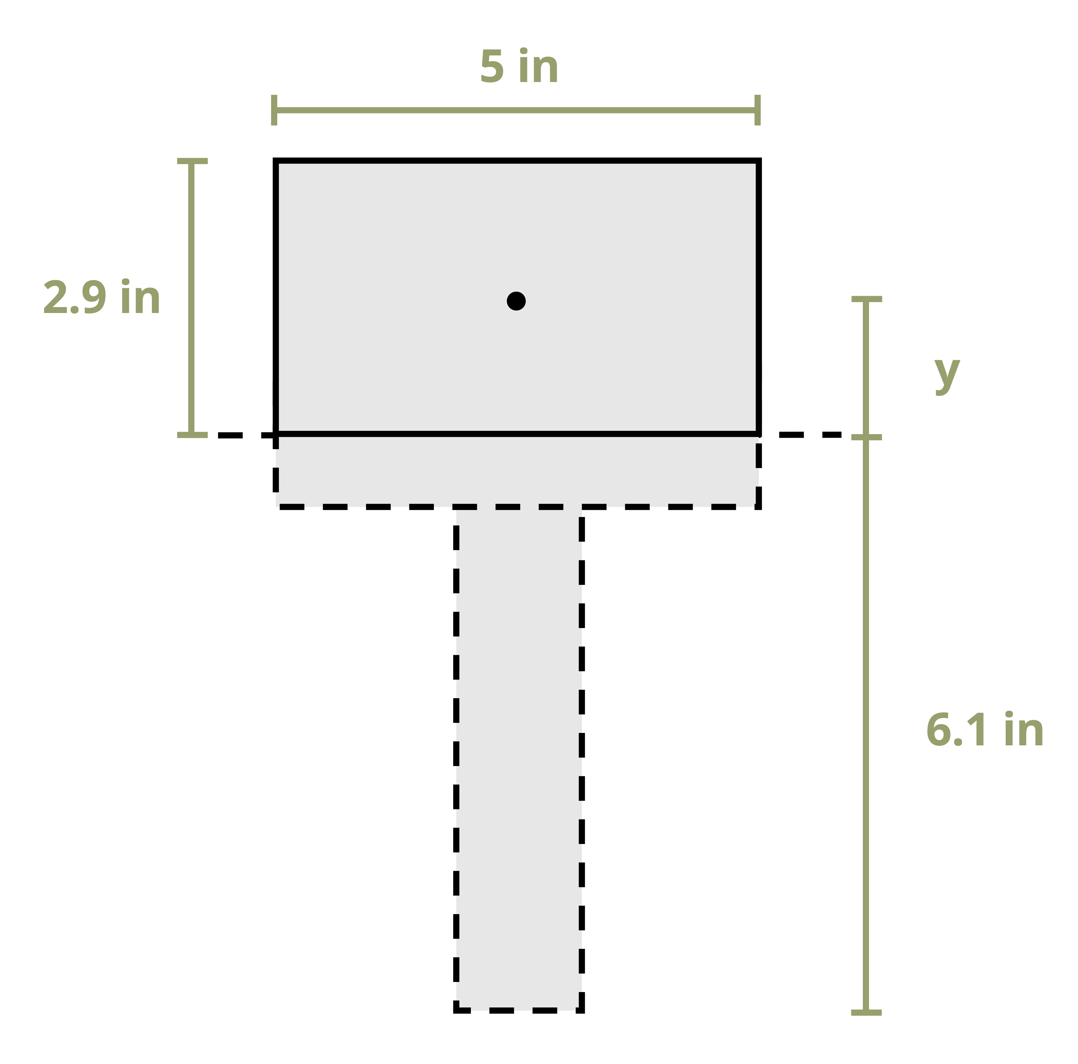
A beam with the cross-section shown is subjected to an internal shear force of 20 kips.
Determine the following:
- The shear stress at the neutral axis of the cross-section
- The shear stress at the point where the thickness of the cross-section changes
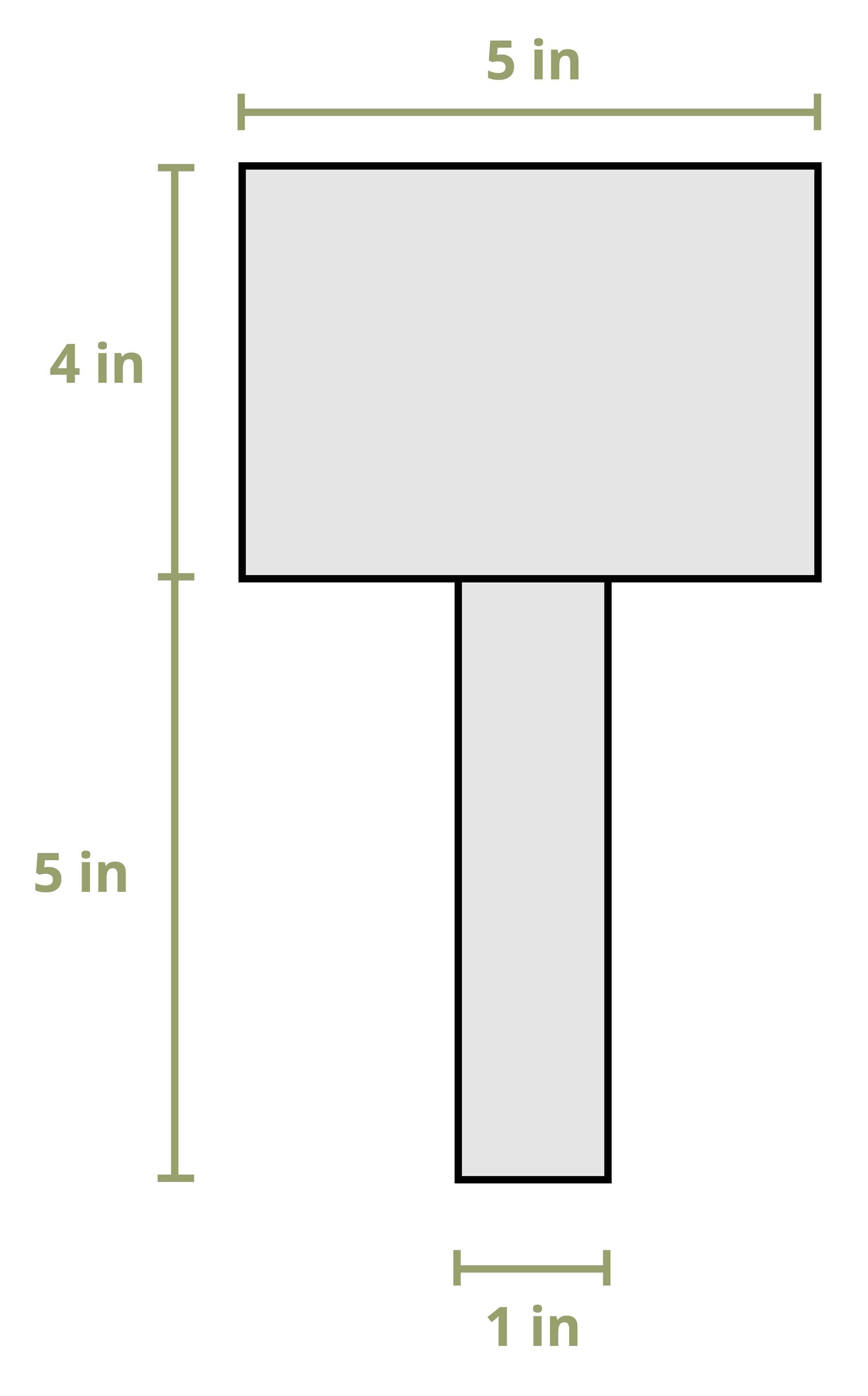
Determine the y-coordinate of the centroid using the method of Section 8.1. Choose the reference point to be at the bottom of the section.
\[ \begin{aligned} & y_1=2.5{~in.},~ A_1=5{~in.}^2 \\ & y_2=7{~in.},~ A_2=20{~in.}^2 \\ & \bar{y}=\frac{(2.5{~in.} * 5{~in.}^2)+(7{~in.} * 20{~in.}^2)}{5{~in.}^2+20{~in.}^2}=6.1{~in.}~~ \text{from the bottom of the section. } \end{aligned} \]
Determine the second moment of area of the entire cross-section using the method of Section 8.2.
\[ I=\left(\frac{1 * 5^3}{12}+5 *(2.5-6.1)^2\right)+\left(\frac{5 * 4^3}{12}+20 *(7-6.1)^2\right)=118.08{~in.}^4 \]
The shear stress at the neutral axis of the cross-section:
Draw a line through the point of interest and use the area above this line to calculate the first moment of area.
\[ Q=y A=\frac{2.9{~in.}}{2} *(2.9{~in.} * 5{~in.})=21.025{~in.}^3 \]
The thickness of the cross-section at this point is t = 5 in.
The shear stress at the neutral axis is then given by
\[ \tau=\frac{V Q}{I t}=\frac{20,000{~lb} * 21.025{~in.}^3}{118.08{~in.}^4 * 5{~in.}}=712{~psi} \]
The shear stress at the point where the thickness of the cross-section changes:
Draw a line through the point of interest and use the area above this line to calculate the first moment of area.
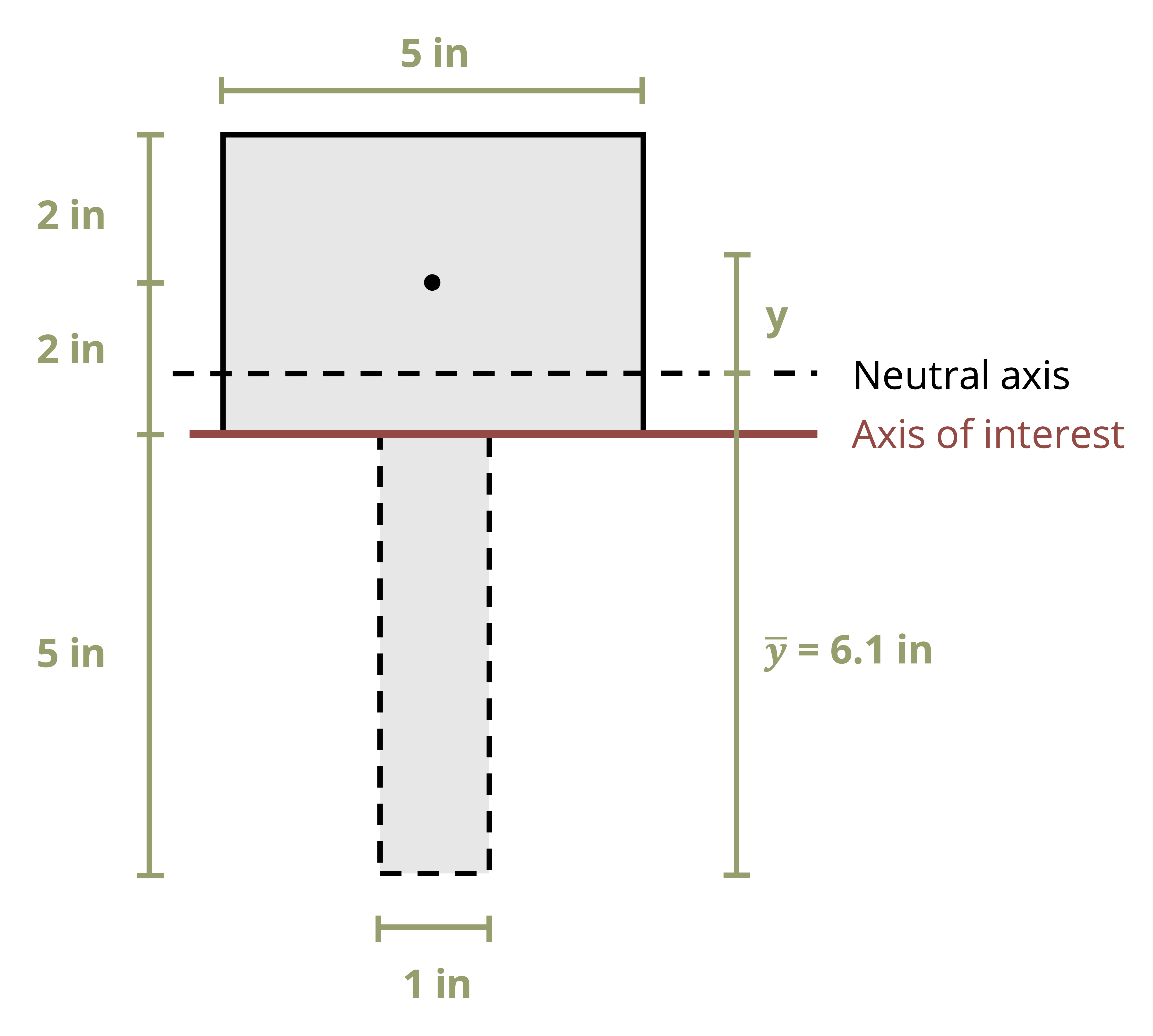
\[ Q=y A=0.9{~in.} *(4 {~in.}* 5{~in.})=18{~in.}^3 \]
The thickness of the cross-section at this point is t = 1 in.
The shear stress at this line is then given by
\[ \tau=\frac{V Q}{I t}=\frac{20,000 {~lb}* 18{~in.}^3}{118.08{~in.}^4 * 1{~in.}}=3,049{~psi} \]
Note that even though the first moment of area is smaller at this axis, the stress is larger because the thickness of the cross-section decreases significantly at this point.
10.3 Shear Flow
Click to expand
Some cross-sections are formed by connecting multiple pieces together with fasteners like nails or bolts (Figure 10.12). In such members we must analyze not only the stresses in the cross-section itself but also the stresses in the fasteners.
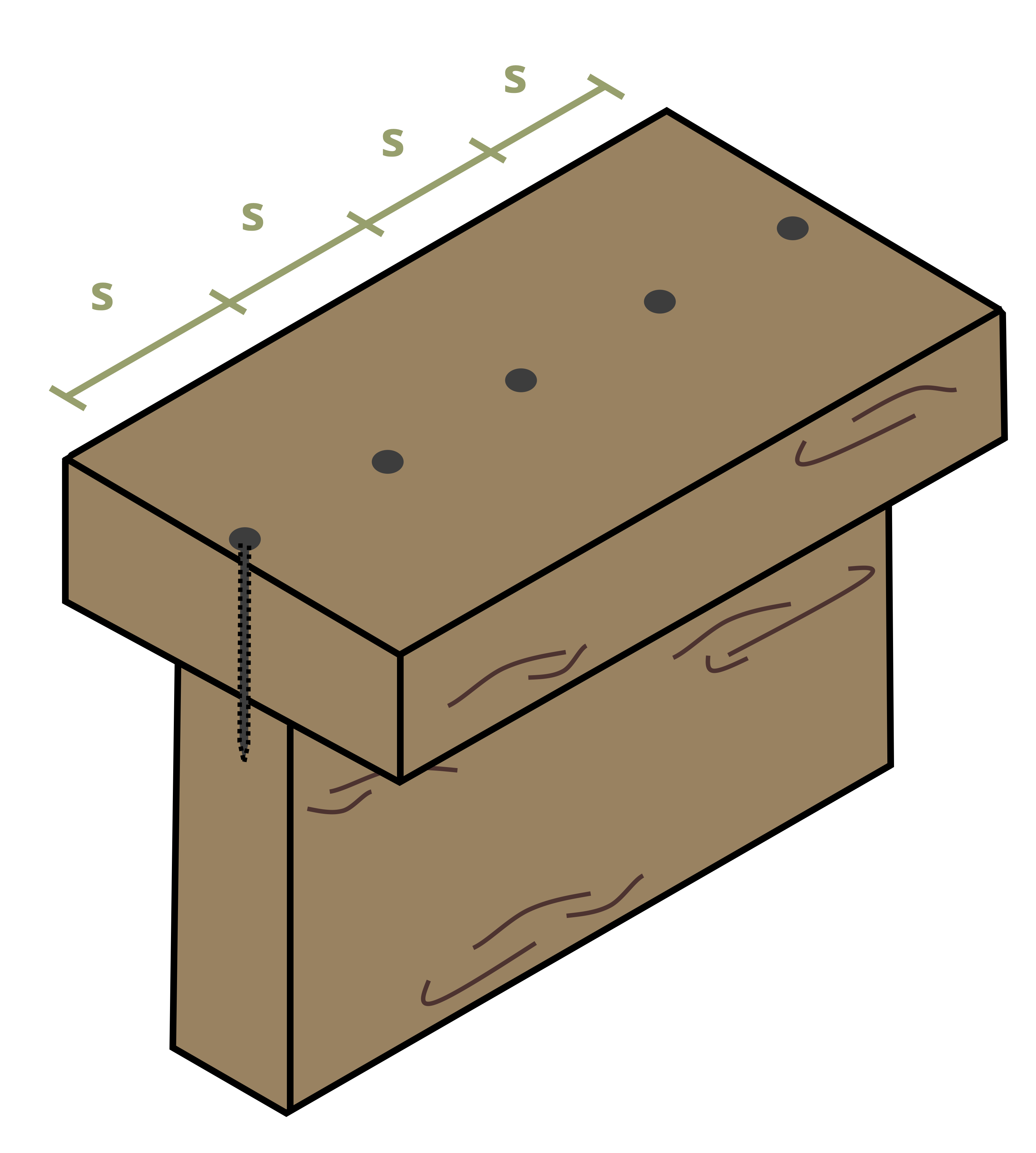
A useful quantity in this regard is shear flow, q. Shear flow measures how much shear force is applied per the beam’s unit length, and is calculated in units of force/length [N/m, lb/in.]. For example, if a nail is capable of resisting a shear force up to 10 kN and there is a shear flow of 30 kN/m, it is trivial to determine that we need at least three nails for every meter of beam.
Recall from Section 10.2 that the internal horizontal shear force, F’, may be written as
\[ F^{\prime}=\frac{\Delta M}{I} Q \]
Dividing both sides by Δx results in
\[ \frac{F^{\prime}}{\Delta x}=\frac{\Delta M Q}{\Delta x I} \]
Similar to the derivation in the previous section, we may replace \(\frac{\Delta M}{\Delta x}=V\). We may also replace \(\frac{F^{\prime}}{\Delta x}=q\). The result is
\[ q=\frac{V Q}{I} \]
This equation is similar to the shear stress equation, but the thickness of the cross-section doesn’t appear here because shear flow is measured per unit length. We will generally want to determine the shear flow at the seam where the individual pieces of the cross-section are joined together as this is where the fasteners must resist the horizontal shear force.
Often it’s necessary to determine how far apart to space the nails along the length of the beam. Since shear flow is the shear force per unit length, if we know how much shear force each fastener can resist, we can say that the shear flow is equal to the force resisted by each fastener (Fnail) divided by the spacing between the fasteners (s). Sometimes there will be multiple rows of nails side by side (Figure 10.13). In this case multiply the force resisted by each fastener by the number of rows (r).
\[ \boxed{q=\frac{V Q}{I}=\frac{F_{nail} r}{s}}\text{ ,} \tag{10.3}\]
q = Shear flow at a line on the cross-section [N/m, lb/in.]
V = Internal shear force at the cross-section [N, lb]
Q = First moment of area at the point of interest on the cross-section [m3, in.3]
I = Second moment of area of the cross-section [m4, in.4]
Fnail = Horizontal shear force resisted by each nail [N, lb]
r = Number of rows of nails resisting the shear force
s = Spacing between nails [m, in.]

Sometimes fasteners may be placed horizontally (Figure 10.14). In these cases still draw a line along the seam perpendicular to the fastener (so vertically here). Then use the area either to the left or right of this line to determine the first moment of area. Note that we still use the vertical distance between the centroid of the chosen area and the neutral axis of the cross-section. For cross-sections with an axis of symmetry, choose to draw either one vertical line and use the area to the left (or right) of this line or two vertical lines, one at each seam, and use the area between (or outside) these lines.
Example 10.5 works through a problem with two rows of nails at each seam.
Example 10.6 involves an L-beam with a horizontal nail.
Example 10.5
A beam is made by nailing together three boards to form the cross-section shown. At each connection, two rows of nails are used to secure the boards. Each nail can resist a horizontal shearing force of 1,500 N.
If the beam is subjected to an internal vertical shear force of 4,500 N, determine the minimum required spacing, s, between the rows of nails.
We need to determine the shear flow at one of the points where the beams are connected. Use \(q=\frac{V Q}{I}\) where V = 4,500 N. Since the section is symmetric, determine the location of the centroid by inspection, \(\bar{y}=160 \mathrm{~mm}\) from the top and bottom. Now determine the second moment of area, I, for the cross-section.
Consider the area as a large rectangle with two smaller rectangles cut out.
\[ I=\frac{140 * 320^3}{12}-2\left(\frac{45 * 200^3}{12}\right)=322.3 \times 10^6{~mm}^4=322.3 \times 10^{-6}{~m}^4 \]
Next draw a line through the point of interest (along the seam where the nails are holding the boards together) and determine the first moment of area, Q, at this line.
\[ Q=y A=130{~mm} *(60{~mm} * 140{~mm})=1,092 \times 10^3{~mm}^3=1,092 \times 10^{-6}{~m}^3 \]
Shear flow is then
\[ q=\frac{V Q}{I}=\frac{4,500 {~N}* 1,092 \times 10^{-6}{~m}^3}{322.3 \times 10^{-6}{~m}^4}=15,247~\frac{N}{m} \]
Finally, set the shear flow, \(q=\frac{F_{nail} r}{s}\), and solve for the spacing, s.
\[ s=\frac{F_{nail} r}{q}=\frac{1,500{~N} * 2}{15,247~\frac{N}{m}}=0.197 \mathrm{~m}=197 \mathrm{~mm} \]
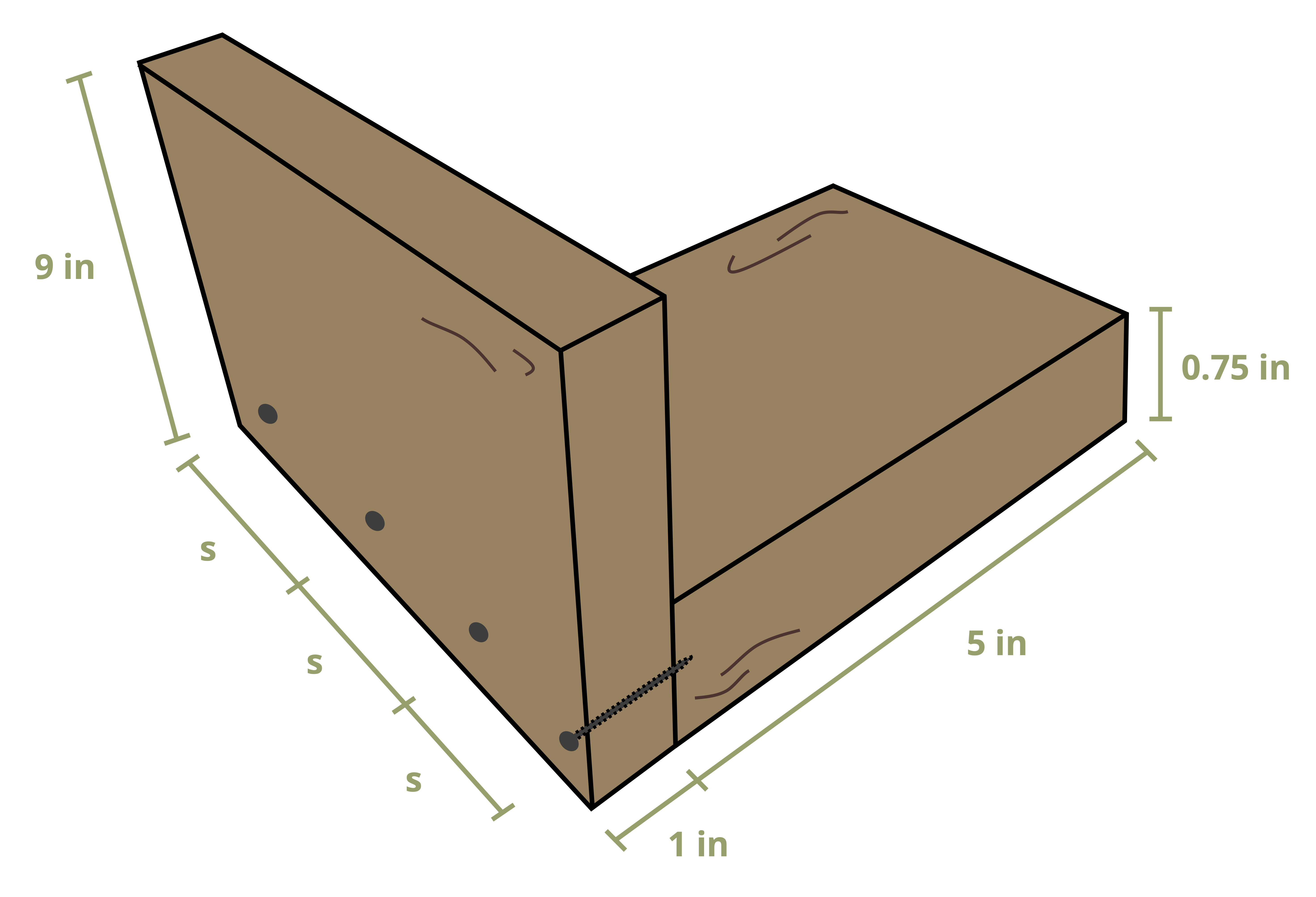
Example 10.6
A beam is formed by nailing two boards together to form the L-shaped cross-section shown. The nails are spaced a distance s = 1.5 in. apart along the length of the beam, and each nail can resist a force of 700 lb in shear.
Determine the maximum allowable internal shear force in the beam.
Determine the allowable shear flow in the beam given the nails.
\[ q=\frac{F_{nail} r}{s}=\frac{700{~lb} * 1}{1.5{~in.}}=467~\frac{lb}{in.} \]
This shear flow can be set equal to \(q=\frac{V Q}{I}=467~\frac{lb}{in.}\).
Find the y coordinate of the centroid of the cross-section, setting the reference point at the bottom of the section.
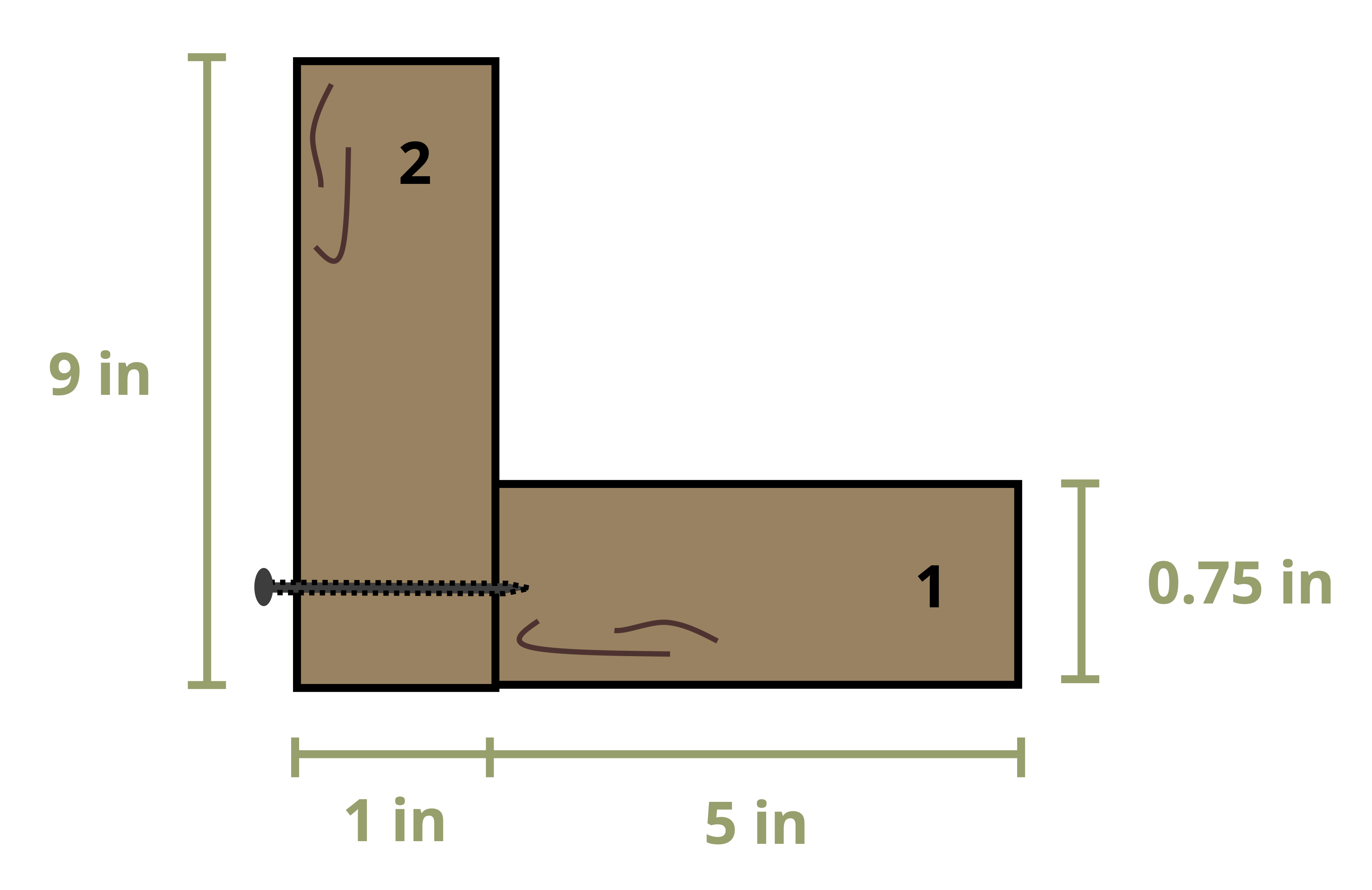
\[ \begin{aligned} & y_1=0.375{~in.}~,~ A_1=5{~in.} * 0.75{~in.}=3.75{~in.}^2 \\ & y_2=4.5{~in.}~,~ A_2=1{~in.} * 9{~in.}=9{~in}^2 \\ & \bar{y}=\frac{(0.375{~in.} * 3.75{~in.}^2)+(4.5{~in.} * 9{~in.}^2)}{3.75{~in.^2}+9{~in.^2}} = 3.287{~in.}~~\text{from the bottom of the section} \end{aligned} \]
Find the second moment of area for the entire cross-section.
\[ I=\left(\frac{5 * 0.75^3}{12}+3.75 *(3.287-0.375)^2\right)+\left(\frac{1 * 9^3}{12}+9 *(4.5-3.287)^2\right)=106{~in.}^4 \]
Draw a line along the seam where the nails are holding the two boards together. Note that this is a vertical line. To determine the first moment of area, Q, we use the area either to the left or to the right of this line. Note that when calculating Q = yA, the distance y is still measured in the vertical direction between the centroid of area A and the neutral axis of the cross-section.
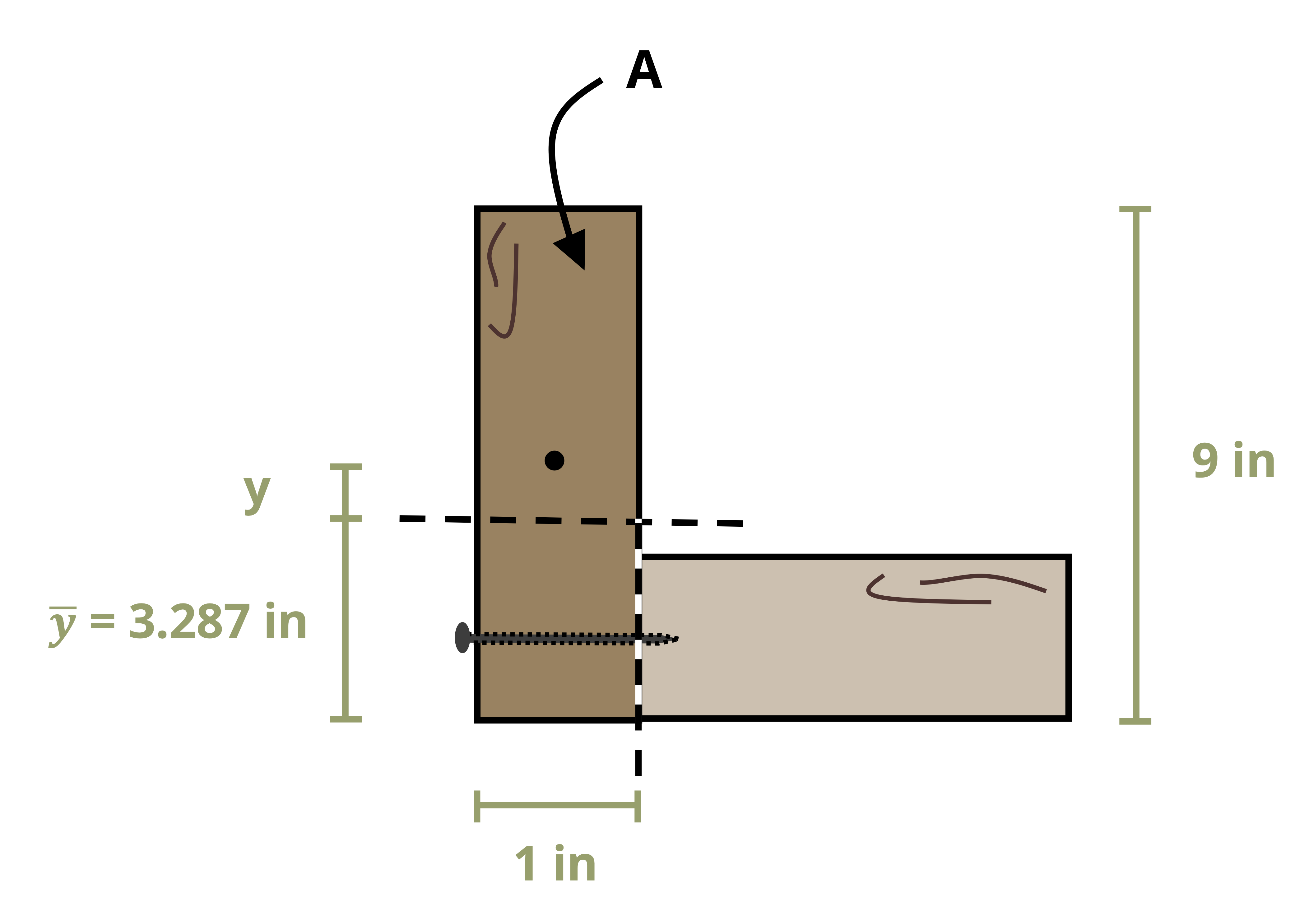
\[ \begin{aligned} & y=4.5{~in.}-3.287{~in.}=1.213{~in.} \\ & A=(1{~in.} * 9{~in.})=9{~in.}^2 \\ & Q=1.213{~in.} * 9{~in.^2}=10.9{~in.}^3 \end{aligned} \]
Finally, solve for the maximum allowable internal shear force in the beam by rearranging the shear flow equation.
\[ V=\frac{q I}{Q}=\frac{467~\frac{lb}{in.} * 106{~in.^4}}{10.9{~in.^3}}=4,541{~lb} \]
Summary
Click to expand
References
Click to expand
Figures
All figures in this chapter were created by Kindred Grey in 2025 and released under a CC BY license, except for
Figure 10.7: A stack of papers representing a beam. James Lord. 2024. CC BY-NC-SA.
Figure 10.8: Horizontal shear failure in a wooden beam subjected to a vertical load. Figure 8 in Adam Derkowski, Marcin Kuliński, Adrian Trociński, Jakub Kawalerczyk, and Radosław Mirski. 2022. Mechanical Characterization of Glued Laminated Beams Containing Selected Wood Species in the Tension Zone. Materials 15(18), 6380. https://doi.org/10.3390/ma15186380. CC BY 4.0.